| Summary |
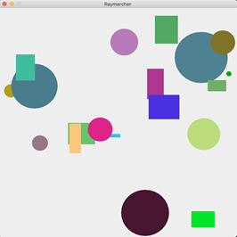
Two-dimensional ray marcher, experiments with random shape generation, primitive collision detection,
object-oriented programming, mouse/keyboard input. |
| Audience |
This lab is primarily aimed at students with at least a semester’s worth of programming (i.e., loops,
conditionals, variables, arrays), preferably in Java. The student does not need any experience with graphical
user interfaces or libraries - we walk the students through these components. Object-oriented programming
paradigm knowledge and understanding is essential (i.e., methods, classes, polymorphism, abstract classes,
interfaces). |
| Difficulty |
A second semester (or in-progress) student should be capable of completing this lab. A strong first semester
student may be able to with time. |
| Topics |
Ray marching, Computer graphics, collision detection, sphere tracing |
| Strengths |
Allows the student to see how collision detection techniques work compared to naive approaches. Students are
exposed to rendering graphics, data structures, polymorphism, abstract classes, interfaces, and mouse movement
and input. |
| Weaknesses |
This is a long lab, taking around two to three hours to do in one sitting with a fairly competent student.
This could serve as a one to two week homework assignment. The lab also requires knowledge of some basic
trigonometry. Further, it relies on the student understanding a good amount of Java (or at the very least the
ability to pick it up fast). |
| Dependencies |
In the current iteration, this lab depends on Java Swing. Though, this could easily be ported to another
framework like JavaFX or an entirely different language like C or C++ with SDL and SFML. For convenience,
though, we include starter code using Java and Java Swing. |
| Variants |
Variations include using different shapes, gradients as colors, camera panning. |
By the end of this lab, students should be able to use iteration to determine the
distance between a point and
several objects in a plane, change angle-of-view and position via mouse input, and modify graphics/shapes in a
plane. Students should also be able to understand the benefits of raymarching over other two-dimensional collision
detection techniques.
Today's world of computing is filled to the brim with colorful and life-like graphics
- continuing to blur the line
from fantasy and reality. Has it ever occurred to you to think about how games, animators, and others create these
amazing works of art? In this lab, we're going to explore the topic of sphere-tracing: a type of ray marching
algorithm.
First, let's back up and understand what ray tracing is, since ray marching is a
derivation. Ray tracing involves a
camera and an environment (also called a world). The camera projects simulated lines called rays into the world
which then interact with objects in the world. Think of it like a light source; light travels from its source to
objects which is then reflected and altered based on the colliding object. Try to imagine how a computer would need
to do this. A computer has to, mathematically, determine when a collision with an object occurs so as to not
erroneously pass through that object (we're ignoring translucency!). A naive solution is to extend, or march, the
ray outward in intervals of a predetermined unit, checking for collision along its path. This raises an obvious
question: what is a unit, and what about the interval? Look at the diagram below.
Note that the star is the camera (i.e., where our ray begins), and the purple line is
a wall, or an object. If we
assume our ray checks for collisions every 2 squares, then the ray passes right through the object! The solution
would be to change our frequency to checking for collisions every one square. Though, imagine this world is
significantly bigger. If we check for collisions too often, it's slow. Conversely, too few implies the possibility
of missing an object. Sphere tracing provides a happy medium.
- First, download the accompanying RaymarchingLab.zip file (listed above). Inside, you will find
three
Java classes:
RaymarcherRunner, RaymarcherPanel, and SwingApplication. The latter
SwingApplication initializes boilerplate code
for the front-end Swing components, so unless you are interested, it is not necessary to investigate this code
further. There are a few methods that we use, but the underlying implementation is beyond the scope of this lab.
This lab was designed with the Eclipse IDE, but it can work with or without an IDE.
- After setting up the project, get accustomed to the two other classes. The main class,
RaymarcherRunner, as the
name suggests, runs the application and initializes all GUI components. On the other hand,
RaymarcherPanel is
where you will be doing most of the laborious work. This JComponent object is called a
JPanel. In short, rendering
and drawing should occur on this panel object. To test your environment, we have included a couple lines of code
that draws a blue rectangle on the screen inside the paintComponent method using the
Graphics2D class. Play around
with this to see if you can try different colors or even different shapes. Remove these lines (except the first
two) once you are done experimenting.
- Since we’re going to be creating an environment for rays to collide with, we obviously need objects for the ray
to collide with, right? So, let’s do that. Create two subclasses called RectangleObject and
CircleObject that
extend an abstract superclass CollisionObject. The idea is this: we’re going to populate our world
with random
rectangles and circles. A CollisionObject should have, at minimum, an \((x,
y)\) coordinate pair. RectangleObject should
have width/height fields, and CircleObject should have a radius/diameter field, whichever you prefer
(note which
one you use to construct the object because it will be relevant later).
 Warning! Make absolutely sure that you use double or float variables when
initializing positions. When drawing with Swing, you can do one of a few things: either create objects with the
java.awt.geom package that allow for explicit doubles when instantiating shape objects (e.g.,
Line2D, Rectangle2D,
Ellipse2D) and then draw those with g2d.drawShape(), or cast doubles to integers and use
other methods in
Graphics2D. Later on when we perform arithmetic on the positions and dimensions, floating-point
operations are
crucial to ensure we don’t encounter integer truncation issues.
Warning! Make absolutely sure that you use double or float variables when
initializing positions. When drawing with Swing, you can do one of a few things: either create objects with the
java.awt.geom package that allow for explicit doubles when instantiating shape objects (e.g.,
Line2D, Rectangle2D,
Ellipse2D) and then draw those with g2d.drawShape(), or cast doubles to integers and use
other methods in
Graphics2D. Later on when we perform arithmetic on the positions and dimensions, floating-point
operations are
crucial to ensure we don’t encounter integer truncation issues.
Warning! If you’re trying to set the positioning based on the
screen/window size, you’ll need to use this.getPreferredSize().width and
this.getPreferredSize().height. This is
because the JPanel hasn’t been packed into the parent JFrame component when the
CollisionObject are instantiated.
Warning! Keep note of whether the objects are instantiated at the center
or the top-left. Whether you do either or is up to you, but if you instantiate them at the center now, it’s
slightly less effort later. Otherwise, you have to do a bit more later on since we’ll be working with the center
of objects.
 Try this out: if you are familiar with
vectors, writing
your own small 2-D vector class to handle positioning,
dimensions, and movement is extremely beneficial!
Try this out: if you are familiar with
vectors, writing
your own small 2-D vector class to handle positioning,
dimensions, and movement is extremely beneficial!
- Now, you may be wondering: “Where do we instantiate these objects?” Well, we can populate them in the
RaymarcherPanel class. Create a list of CollisionObjects with random dimensions and
positions. The size of the
list doesn’t necessarily matter, but try to keep it lower than twenty (20) objects. Also, make sure that objects
do not generate outside the world!
- At this point, you should have a fully populated list of CollisionObjects. It is now time to draw
them! Note
that JComponents have the paintComponent(Graphics g) method for drawing. We’re going to
do something similar.
Since we’re going to be drawing objects besides CollisionObjects, we should create an interface that
says
something is “drawable”. Create an interface called Drawable with the method signature void
drawObject(Graphics2D
g2d). From here, implement the interface in CollisionObject and override its method in your
subclasses. Now, add
the functionality to draw the shapes. Finally, in your panel class, iterate over your list of objects and call
drawObject on each one. When drawing the objects, draw them at their center! Drawing them at the
top-left causes
severe problems down the road. So, make sure you apply the correct math offsets to draw the shape at its center
(note that I said draw at the center; not position at the center. If you position at the center then
you’ve
already done this part!).
Try this out: give each shape a random
Color
attribute! The Graphics2D method
setColor(java.awt.Color) may be useful!
- We’re now ready to start our ray marcher! The first thing we need is some type of “camera” or perspective to
start at. It also would be a little boring if we could only march rays in one direction, right? So, we’ll need to
add a listener to our camera, but we’ll get to that as we go. Firstly, Create a class called Camera
and another
called March. Camera will be where the ray begins marching, and March will
be a single step, or iteration, in the
ray march. Both of these will have \((x, y)\) coordinates and radii. This is
almost identical to the CircleObject class,
and we could reuse it, but because they serve different purposes (and we’re going to add more to it), we’ll just
rewrite a new class. We’ll first write the Camera class since it is more interesting.
- Camera, as we mentioned earlier, is the starting point of our ray march. So, like
CollisionObject, we’re going
to implement Drawable. The camera is just a small circle, so giving it a fixed radius of, say, ten
(10) pixels is
sufficient. Do the same thing you did for CircleObject: draw the camera at the provided x and y
coordinates.
- Now, we’re ready to move our camera! There are two ways we can do this: with keyboard input or mouse input. We
will choose the latter. As we move the mouse around the world, we want our camera to follow us. Thankfully, Java
provides a very nice MouseMotionListener interface for us to implement. Once Camera
implements this, you will be
required to override two methods, but we only need to write code inside one: mouseMoved(MouseEvent).
Whenever we
move the mouse, we want to update the \(x\) and \(y\) coordinates of Camera. Any time the mouse is moved, the mouseMoved
method is called, and the MouseEvent parameter contains two methods: getX() and
getY(). So, assign the coordinate
instance variables of Camera to these values in this method.
- The only thing that’s left is to register the motion listener with the panel. So, create an instance of
Camera
inside the RaymarcherPanel constructor. Call addMouseMotionListener and pass it the
Camera object. Also, don’t
forget to call drawObject from Camera inside RaymarcherPanel’s
paintComponent method or you won’t see anything!
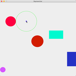
Run the program and you should see your camera move as you move the mouse.
Warning! If you place the camera’s draw method above the loop where you
draw the objects, you won’t see it if your mouse is over an object. Can you deduce why?
Try this out: If you assign the \(x\) and
\(y\) coordinates to the exact position of the mouse event’s \(x\) and \(y\) coordinates,
it will
be slightly offset. Try and find out why and how to fix it (note that it has nothing to do with the assignment
itself!).
-
Now, let’s begin the raymarching! As we mentioned, we’re going to implement sphere tracing, where we compute
the minimum distance between the mouse and all objects in the scene. So, we first need to understand how to
compute this. We’re essentially computing the hypotenuse of the triangle formed from the center of the camera to
an object’s center. So, let’s look at this for both cases.
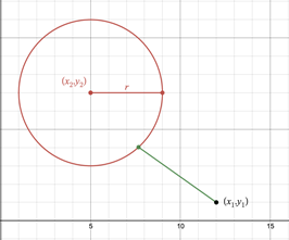
For circles, We need to account for only one thing: the radius. Take the distance (also called the magnitude if
you’re familiar with vectors) from the camera to the center of the circle and subtract its radius. The formula
is as follows:
\[
d = \sqrt{(x_1 - x_2)^2 + (y_1 - y_2)^2} - r
\]
Where \(x_1\), \(y_1\) represent the
coordinates of the camera’s center, and \(x_2\), \(y_2\) represent the center of the circle. \(r\)
is the radius of the circle. In the figure below, we want to compute the magnitude (length) of the green line).
This is \(d\) in the above equation.
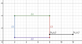
Rectangles are a bit more complicated since we’re involving both width and height instead of just a radius. The
simplest way to do it is to compute the distance between the camera and the line segments that make up the
rectangle. Line2D provides a great method for computing this distance: ptSegDist.
There are four line segments
that make up each rectangle, so just take the minimum of all four segments. Note that creating the line segments
is ever so slightly harder (not by much at all!) if you chose to center the rectangle instead of using its
top-left coordinate. In the figure below, note that each line segment is denoted by \(L_1\), \(L_2\), \(L_3\), and \(L_4\).
Recreate this in your program using the aforesaid methods. A good idea would be to create an abstract method
computeDistance(double cameraX, double cameraY) in CollisionObject which is overridden
and implemented in your
subclasses. Tips: This step will most likely take the most amount of time so use the Swing classes to your
advantage! Point2D, Line2D, etc. are all helpful!
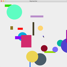
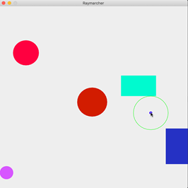
- Now, iterate through your list of objects and compute the minimum distance between the camera’s position and
each object. Use this distance to draw a circle at the camera’s center with a radius of the minimum distance
multiplied by two (think about why we do this!). As you move the mouse around the screen, you should notice
that
the circle is drawn out to touch the nearest object.
Warning! If you only multiply the distance of the circle by two and don’t
adjust where the circle is drawn, your circle will be drawn at an incorrect spot! So, be sure to multiply the
distance by two, then draw it at the camera’s center.
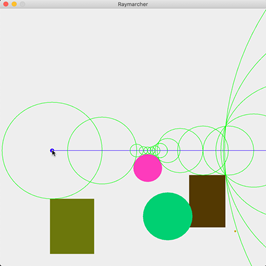
- We’re almost there! What we need to do now is actually cast multiple marches out into the world instead of just
one. The idea is as follows: march out as far as you can until you collide with something. Compute the minimum
distance from that point to every other object in the world and march out to that point. We need to eventually
stop marching if the march has a small enough radius (say, 0.01). If the minimum distance from the current point
to any other object is smaller than this threshold, we can deduce that we have collided with something and cast
the ray. Let’s start with the March class.
- A march consists of four primary things: a circle, line, a starting point, and an ending point. The line’s
length should be equal to the radius of the circle. Create the March class with these properties.
Then, implement
the drawing functionality.
- A ray consists of multiple marches. So, we can create a Ray class that receives a list of
March objects. When
drawing the ray, draw all the marches that are in its list.
- Lastly, we need to add this new functionality to the panel. You should use a loop to keep track of the minimum
distance between the current iteration point and any object in the world, and once this goes below that threshold
mentioned in step 12, break out, then initialize and draw a Ray. When marching, the next point should
be created
at the current point plus the length of the march (with no alterations to the y coordinate - see step 16 for more
on this!).
Warning! If your program is freezing, check to make sure that your
distance functions are correctly computing the minimum distance, and that your threshold isn’t too low (below 0.01
can cause floating-point precision errors). Also, when setting up the loop to continue until the minimum distance
is below the threshold, you most likely want a do-while loop because you want at least one iteration to complete
prior to breaking out. Further, you may want to keep track of the ending position of the current point in the
march - if it goes beyond the screen, you should terminate the loop! Finally, if you’re noticing that, as you move
the mouse closer to a point that it suddenly locks up, check to make sure all coordinates are floating point and
non-integer!
Warning! The same bug with the circle’s rendering location occurs here if
you don’t offset it like step 11 informed you.
- This is nice, but wouldn’t it be neater if we could rotate that ray? It sure would be! First, let’s consider
what is going on when marching. As we said in step 15, we’re only advancing along the x-axis and not the y-axis.
This makes drawing our marches (and hence the ray) easy since there’s no trigonometry involved. But, to advance
along both axes, we need a new field in the Camera class to keep track of the angle. After this, we
need a way of
modifying said angle. There are a few ways to do this, but we’ll go with a mouse approach again. Let’s suppose
that when the user clicks the left mouse button, their camera angle will increase, and decrease if they click the
right mouse button. To implement this, we need to use the MouseListener interface, and again, it will
require that
you import a whole bunch of methods but we only need to use one: mousePressed(MouseEvent).
- In mousePressed, a MouseEvent is supplied, just like mouseMoved. The difference is
that we will be using the
getButton method to determine which button was pressed instead of checking for position. To check which button was
pressed, use event.getButton() == MouseEvent.BUTTONX, where X represents the button (1
is
the left mouse button, 3
is the right button). Write the code to increment the angle by 1 if the left mouse button was pressed, and
decrement by 1 if the right button was pressed. After this, add the Camera instance as a
mouseListener object to
the panel.
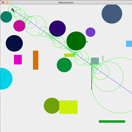
-
So, this doesn’t change much if you run it. However, now we can update our ray drawing procedure. To do this,
we can use polar coordinates.
We have our starting coordinate pair \(P_1\), and the minimum distance from
\(P_1\)
to
any object in the plane is \(l\). The
camera’s angle is \(t\) in radians. We wish to compute \(P_2\), the ending coordinate pair to this line. Thus,
\begin{align*}
P_{2_x} &= P_{1_x} + l \cdot \cos(t)\\
P_{2_y} &= P_{1_y} + l \cdot \sin(t)
\end{align*}
Use this logic to update your code and see what it does now.
Try this out: You may notice that constantly
clicking the
mouse to change the angle is a bit cumbersome. Use some of the other MouseListener methods to change
this
functionality!
- And that’s it! You’ve successfully created a sphere tracing ray marcher. Continue to add new things such
as different shapes! You can add triangles and polygons in the same way that we did the rectangles.